In the previous post, we took a look at the basics of the OSI and TCP/IP model layers. In this post we are going to take a closer look at end to end routing of a packet, and the interaction between layers 2 and 3 as a packet is passed between routers to it’s ultimate destination. The following is the general process to route between endpoints. Some operating systems may behave a little different that described, but this is the general process.
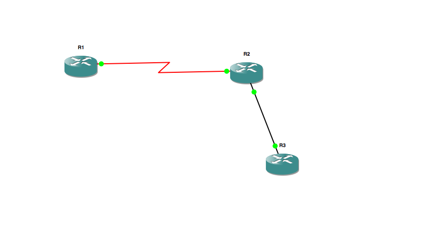
This post will use this network, with a telnet session from R1 to R3. R1 is connected to R2 via a serial link running PPP, and R2 is connected to R3 via an Ethernet segment.
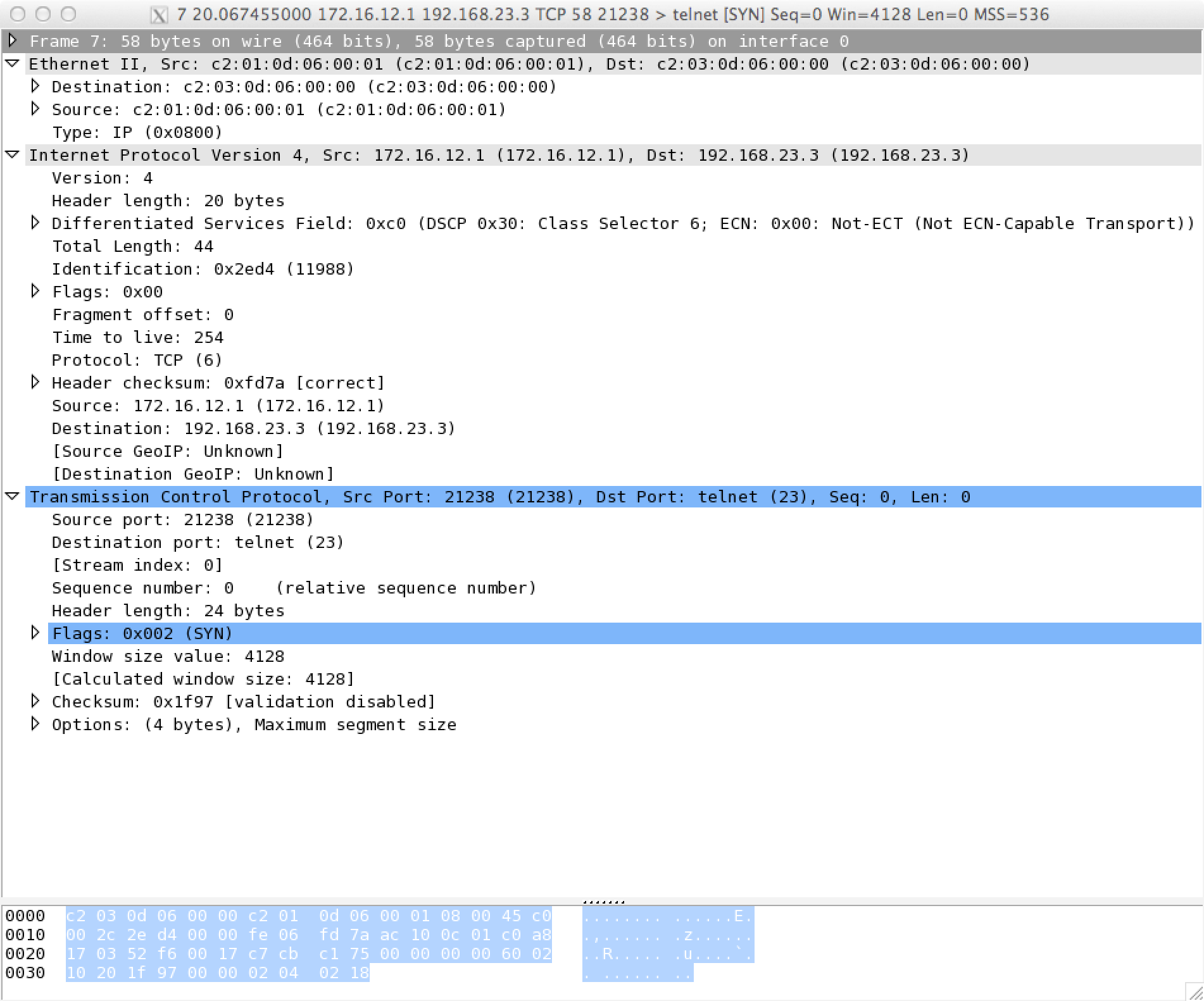
When a network transmission starts, the client host (R1) determines the IP address of the server (R2) that is wants to communicate with, either by the address being entered, or by a DNS lookup of a hostname or Fully Qualified Domain Name (FQDN.) In this case, I opened a Telnet session with the command “telnet 192.168.23.3” on R1. This address may also come from a web address entered in a browser, the DNS server addresses configured on the client, and the like.
The routing process on the the machine sending the packet determines an outgoing interface based on the route table. In this case, R1 and R3 have default routes pointing to the interface the are connected to on R2, so the outgoing interface on R1 is the point to point serial link, running PPP.
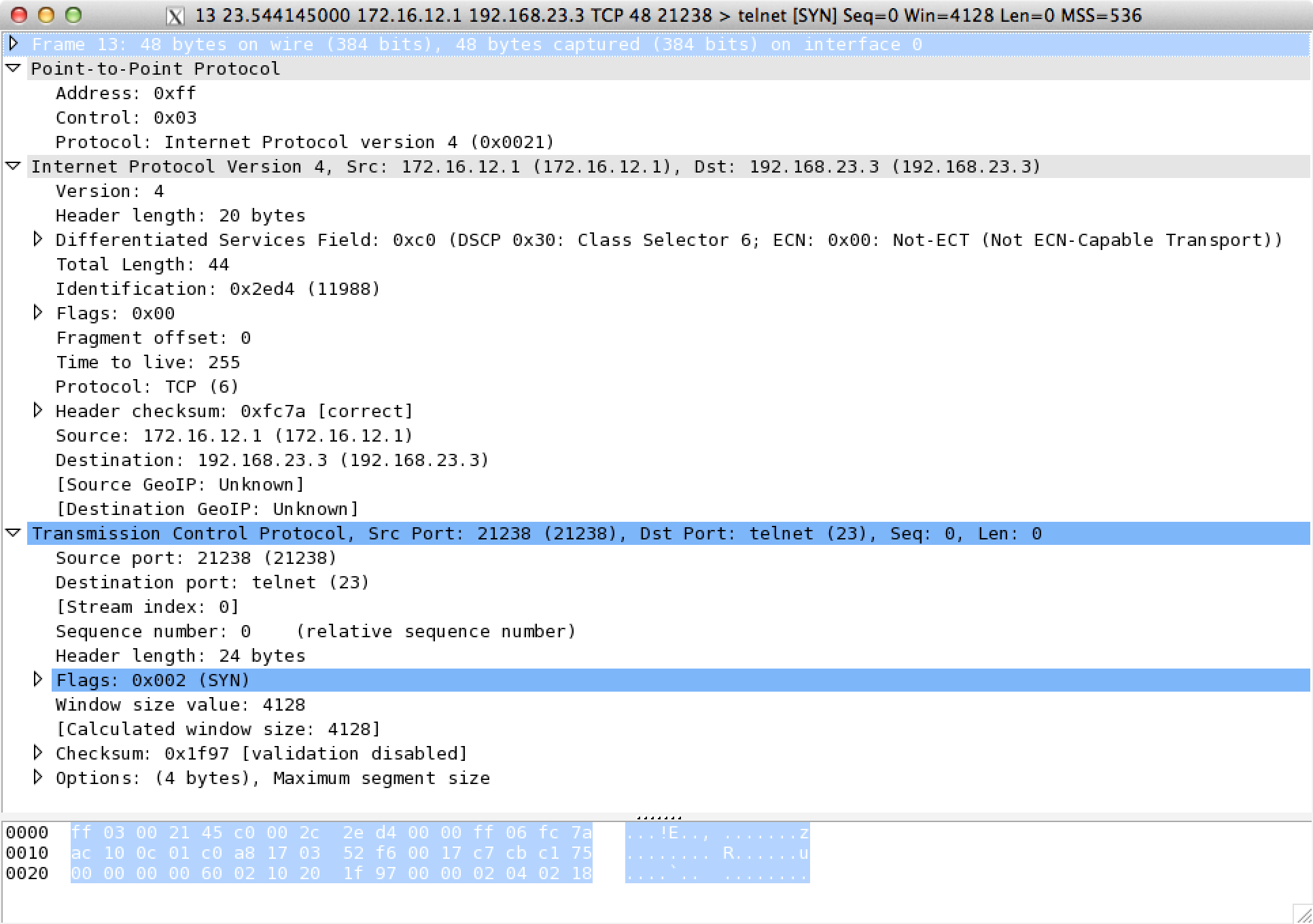
R1 encapsulates the data it needs to send in an IP header, with it’s outgoing interface address (172.16.12.1) as the source address, and the destination IP address from our command (192.168.23.3) as the destination address.
The packet is encapsulated with a PPP header, and sent out the serial link to R2:
Once the packet reaches R2, R2 strips the PPP header, and looks at the IP header below. Depending on QoS or security policies, it may look deeper, for instance ports in the TCP header, but that is beyond the scope of this post.
R2 determines that the destination 192.168.23.3 is on the connected Ethernet interface with the address 192.168.23.2. Because Ethernet is a multiple access Layer 2 technology, R2 needs to address the Layer 2 frame before it sends it out. On Ethernet, this is performed by the Address Resolution Protocol, or ARP.
ARP Example
If R2 does not already have the MAC address of R3 in it’s ARP table, it sends an ARP query as a broadcast on the Ethernet segment:
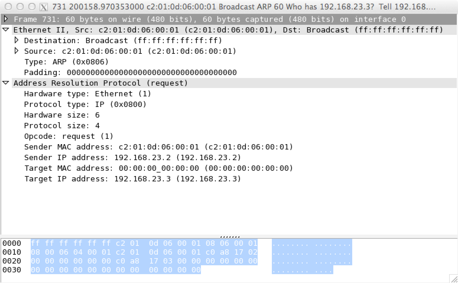
In the ARP request, you can see a number of important points. The destination MAC address is the broadcast address ff:ff:ff:ff:ff:ff, which means all hosts on the Ethernet broadcast domain will process the packet, but only the device with the target IP address will respond. The exception to this is proxy ARP, in which a router with a route to a remote IP address can respond with it’s own MAC address. This is not optimal, since it can create excessively large ARP tables on the client. In the example frame, the optcode is set to 1 to indicate a query, and the target IP address is set to the destination IP of our telnet session. If the next hop was determined to be another gateway, and not the end station, the target IP in this packet would be the gateway address.
R3 processes the ARP request, and since it has the IP address 192.168.23.3, it responds to the request with it’s own MAC address as the sender:
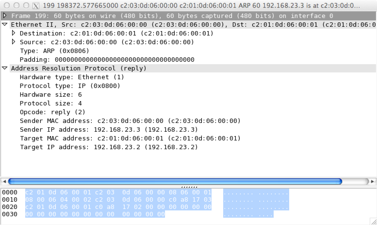
In this case, the destination MAC address is set to R2’s MAC, which R3 learned from the request packet, and the optcode is 2, to indicate an ARP reply. When R2 receives this packet, it places R3’s MAC address in it’s ARP table, and can then encapsulate our original Telnet packet for Ethernet transport:
If you match this frame up with the first one, you will notice that everything from the IP header on is the same. R2 simply takhttp://routeswitchblog.com/wp-admin/post.php?post=383&action=edit&message=10es all the data past the PPP header in the original frame, and attaches the Ethernet header to it, using its own outgoing interface as the source MAC, and the address learned from ARP as the destination MAC address.
These processes will be repeated over whatever other networks may be between the client and server, until the packet reaches the other side. The IP, TCP/UDP, and upper protocol data will remain the same end to end, with only the L2 data being swapped. One variance from this is in the case of MPLS transport, which adds a “Layer 2.5” header to the packet for part of it’s trip. In this case, the MPLS label is effectively an extension of the L2 header, with the IP headers on up behaving the same way they normally do.
Hopefully this helped you visualize the transport of packets across a network. If you have further questions, please leave them in the comments.
Pingback: Practical OSI Layers – Part 1 | Route, Switch, Blog