Configuring Users with Mobile Connect (Single Number Reach)

Mobile Connect is Cisco’s trade name for what is often called Single Number Reach, or SNR. It extends a call to a user’s desk phone out to up to ten other phones, such as home and cell phones. This allows an employee to disseminate a single number, which can always be used to reach the user. This benefits customers and business partners, since they don’t need to try multiple numbers to reach someone, and the employee, since there is no way for the caller to know if you are in the office, at home, or on a golf course.

To do this, UCM makes calls to the PSTN for each off net destination, which requires some planning.While a call is being extended, this ties up one channel per remote destination, up to 10, plus the incoming call, if it is a PSTN call. Once the user answers on a remote device, up to 2 channels are taken up, one for the inbound call, one for the remote device, assuming they are both PSTN devices. The additional trunk usage should be taken into consideration before enabling Mobile Connect.

System Setup

The only real non-default setting for mobility is to create a new softkey template that includes the Mobility softkey. Normally, I would copy the “Standard User” softkey template to something like “Mobility User” and add the Mobility softkey to the On Hook, and Connected call states.

User Setup

Setting up Mobile Connect can be a bit frustrating due to some order of operation considerations. To remember the order of operations, I use the mnemonic UPPeD, standing for User, Phone, (Remote Destination) Profile, and (Remote) Destination.

Continue reading

Default routing options

There are a number of different ways you can implement a default route in IOS. The method you choose depends on the circumstances (routing protocol used, equipment being configured, etc.) and your design goals (such as static vs. dynamic routing.)

ip default-gateway

The ip default-gateway command only works on a device not running IP routing. The most common uses of this command are L2 switches and access points, although it could theoretically be used on something like a voice gateway with only one connection, and the no ip routing command configured. Frankly, I cannot think of any advantage or doing this over a static route. Continue reading

MPLS basics

Over the last several years, we have seen a large push towards MPLS from carriers, and it has been added to the topics for the CCIE R/S.

When I started studying MPLS, I had a bit of trouble wrapping my head around it. I think the biggest reason for that is a basic misunderstanding; The MPLS that we are familiar with from carriers is actually MPLS VPN, so I was expecting that sort of behavior out of the underlying technology. This is kind of like trying to understand IP while expecting it to act like IPSec.

At a basic level, MPLS is a “Layer 2.5” encapsulation that is used primarily for forwarding IP packets, although there are other uses. It inserts a label (sometimes called a tag, especially in older versions of IOS) between the L2 and L3 headers.

 photo headers.gif

In this Wireshark screenshot, we can see the MPLS label is sandwiched between the L2 (PPP, in this case) and L3 (IP) headers.

The label consists of a label number (16, in this case) the Experimental bits, now used for QoS purposes, the Bottom of Stack (BoS) bit, and a Time to Live (TTL). The BoS bit indicates the last label, in case the packet has more than one label applied, for instance for MPLS VPN. The TTL functions like the TTL in IP, getting decremented at each hop.

Without anything like MPLS VPN running over it, the process goes something like this:

  1. The routing protocol on the router populates the routing table.
  2. Label Switch Routers use LDP to advertise a label value for each Forwarding Equivalency Class (FEC), such as IP route, or BGP next hop, to their neighbors.
  3. Each router builds it’s forwarding table (the CEF table on Cisco routers) based on the IP routing table and the label binding received from the next hop router.
  4. When the router receives a packet on an interface with a specific label, it looks up that interface/label combination, and finds the outgoing interface, label value, and L2 information, like the MAC address, of the next router. The router then swaps the incoming label for the outgoing label of the next router, encapsulates the frame, and forwards it.

The preceding is a simplified explanation of the steps, and in this very basic scenario, it doesn’t seem like there is much benefit to MPLS, and, if fact, with the speed modern routers can route IP, it seems to add unnecessary overhead. Generally MPLS would be used either for additional application such as MPLS VPN

BGP learned prefixes

While most routes are added to the Label Forwarding Information Base (LFIB) by IP prefix, BGP routes are added by next hop. With this behavior, all the interior routers in a BGP network need is a route and label mapping to the Provider Edge (PE) routers, not to the individual prefixes.

 photo topology.gif

For example, we have a regional service provider, and we will look at a path from a customer to an upstream network. PE1 is the router between the regional carrier and the upstream network, PE2 is the connection to the customer, and P1 is a router internal to the carrier.  PE1 and PE2 are running BGP, and set next-hop-self on routes that they advertise, using their loopbacks. P1 is not running BGP, all three are running OSPF for routes internal to the provider network. PE1 advertises a tag to P1 (Actually, it would normally be to send an implicit-null, called Penultimate Hop Popping), and since P1 has a route to PE1’s loopback, it advertises a tag value to PE2. When PE2 receives a packet routed via BGP to the PE1, it uses the tag for PE1’s loopback. When P1 receives a frame from PE2, it does not have a route to the final destination, but knows from the incoming label  that the packet should be sent to PE1. It swaps the incoming label for the one that PE1 expects on traffic bound to it’s loopback, and forwards the frame.

The benefit to this is that the internal routers do not have to participate in BGP, saving resources on the routers, and administrative overhead in maintaining peerings. One disadvantage is that if a frame becomes unlabeled, the internal routers are not able to forward it.

Penultimate hop popping (PHP)

In the example above, PE1 would need to do a label lookup to determine that the packet was intended for it’s address, and then an IP lookup for the packet. P1 has to do a label lookup and swap. An optimization is to have P1 simply pop the label, then forward the packet to PE1 as an IP packet. In this case, the lookup and swap is basically the same on P1, but eliminates the label lookup on PE1. This is referred to as Penultimate Hop Popping.

MPLS VPN

MPLS VPN adds to the behavior for BGP by adding another label on the ingress router. BGP shares a label value between the two edge routers for the VPN. The VPN ingress router adds this to a packet bound for the remote VPN destination, then adds a second label for the path to the loopback of the egress router. As the packet is passed between the internal routers, only the “outer” label is swapped, until the packet arrives at the egress router, which pops (removes) the transport label, then looks up the VPN label, pops it, and forwards the packet to the VPN for that label.

The descriptions here are meant to be a high level look at MPLS, and are missing details and some possible options. Look for more MPLS posts here, or check out MPLS and VPN Architectures or MPLS Fundamentals.

Configuring Router on a Stick

Router on a stick (or One Armed Router) is a common name for a configuration used for routing between VLANs on a single Ethernet (including Fast/Gig/10Gig) interface. This configuration uses sub-interfaces on the separate VLANs and an 802.1q or ISL trunk to perform the routing. There are a few reasons you would use this configuration, and several not to. Probably the most common reason is cost. Most branches will have a router for WAN or internet access, using the same router for routing between VLANs saves the cost of a Layer 3 switch. You may also wish to make use of some of the more advanced features on a router, such as firewalling.  Another thing that cuts both ways is that you gain some simplicity by minimizing the number of routing devices, but you add complexity to the configuration of the router. The main drawback is performance. You are pushing all your traffic between two VLANs through a single interface, which could become a network bottleneck. You have to determine the potential impact to your network. The topology and network usage will largely determine how big an impact this will have. If you have all your PCs on one VLAN, and a couple servers that you are doing large file transfers with on another, and your printers on their own VLAN, you are probably going to see some serious issues. Conversely, if you have a single data VLAN, a wireless VLAN, and a voice VLAN, with the majority of the traffic from each going back to a central site over a WAN connection, this may be a very legitimate production use of router on a stick.

Continue reading

UCCX Automatic Call Distribution (ACD) Part 2

In my last post, we looked at configuring UCCX Queues, Skills, and Resource Groups. In this post, we will look at Agents, Supervisors, and Teams. These are how UCCX manages the call center employees. Agents (or Resources) are the people that  answer the incoming phone calls, or are assigned outgoing calls. Supervisors are usually the call center managers, although this capability may be assigned to other people, such as marketing, HR, or IT employees. Teams are administrative groupings of agents, supervisors, and queues.

Configuring Agents (Resources)

In UCCX, agents are referred to a Resources. A Resource can be assigned skills, be assigned to a Resource Group, or both. Agents are the people that calls are directed to, based on skills or resource groups.

The Agent capability cannot be assigned directly to a user; to make a CUCM user a call center agent, find the end user in UCM end users, and assign the user’s phone as a controlled device. Once you click save, you will be able to select a line from any of the controlled devices as the IPCC (IP Contact Center, one of the various names UCCX has had) extension. The extension used for UCCX must not be shared, and should be the first line on the phone. Once a UCM end user has an IPCC extension assigned, they have the agent ability assigned automatically. Continue reading

UCCX Automatic Call Distribution (ACD) Part 1

Automatic Call Distribution, or ACD, is one of the most fundamental features of any call center software. It includes taking calls, queuing them until a qualified agent it is available, and transferring the call to that agent. There are a number of components that make up ACD in UCCX, which I will address over several posts. This page assumes you have installed UCCX, and run through the UCCX initial setup.

Queues, Resource Groups, and Skills

In this post, we will deal with queues, and the ways to assign agents to them.

Resource groups are a static group of agents that can be assigned to one or more queues.

Skills based routing can be configured to require an agent to be assigned one or more skills, and at a minimum level, before calls can be routed to them, and route the calls to agents based on the skill level assigned to them. Queues can be configured to route based on a number of functions based on the agent’s skill level, high to low, low to high, and based on weighting. Continue reading

UCCX Architecture

UCCX is an application server in the Cisco’s Unified Communications suite that provides basic or advanced IVR, call queuing, Automatic Call Distribution (ACD), agent management like reporting and recording (both built in, and using the Quality Management and Advanced Quality Management products. The basic components required to process calls in UCCX are a Unified Communications Manager cluster, gateways for PSTN access, and a UCCX node or HA cluster.

A CCX HA cluster is based on a Publisher/Subscriber relationship, like UCM, but is an active/passive cluster. One node performs all call processing and the other node is available as a hot standby. When a failover occurs, either administrative, based on a failure, or for instance if a node is restarted, the node will stay active until something causes it to fail back the other node. This is because, since calls can be actively terminated to the UCCX server, failover can cause an interruption of call processing. When a failover occurs, call that are terminated to the CCX server will be lost, while calls actively talking to agents should not be.

The basis of call handling in UCCX is the application, which is a combination of a script, one or more triggers, and zero or more parameters. There are also prompts, queues, agents, and a lot of other pieces, but they center around these 3.

Scripts: Created by a dedicated editor (Cisco Unified CCX Editor) can preform a wide variety of call handling operations (answer calls, transfer calls, collect DTMF digits, play prompts, etc.), interact with CCX queues and agents, process data, etc.

Triggers: CTI route points registered with Unified CM. Ports are used to route a call to a specific application. Triggers can also set the language in a multi-language environment, and can be referenced in a script, so the script can handle calls to individual triggers differently.

Parameters: Values that can be fed to a script to customize it for a specific application.

A single script can be used for multiple applications. For instance, a script could be created that answers a call, plays a welcome prompt, and places the caller in a queue, playing music on hold and a periodic announcement until an agent becomes available. The company using it needs 2 call flows, one for sales, and one for repairs. The call flows are identical, except that the welcome prompt should reflect the department called, and the callers should be placed in the queues called “sales” and “repairs,” respectively. Rather than create a separate script for each department, a single script can be used, that expects parameters for the welcome prompt and the queue name. Then, “sales” and “service” applications are created, with the appropriate values configured as parameters. Then, triggers are assigned to each of them, say 1000 for sales, and 1001 for service. When a person called 1000, UCM rings the trigger 1000 on CCX, and CCX handles the call using the application (script and parameters) assigned to that trigger.

Note that it is possible to create a single script, single application, with multiple triggers, and route the call based on that. I tend to prefer the first way, as it tends to allow for easier administration.

Over some upcoming posts, I will take a deeper dive into these topics, and provide some examples.

Cisco Unified Contact Center Express (UCCX) Initial Setup

Unified Contact Center Express (UCCX) is the solution for small to medium (up to 400 agents) call centers in Cisco’s Unified Communications suite.  It runs on the same UCOS platform that Unified Communications Manager and Unity Connection run on, the initial install is identical. This post takes you from the end of that install to a point where you can configure applications to process calls.

Once UCCX is installed, it will run through a setup wizard when you first log in to the web interface. Before the wizard is run, a CUCM AXL user needs to be configured, and a license file obtained. Continue reading

Cisco Unified Contact Center Express (UCCX) Install

Starting with version 8.0, UCCX is based on the same hardened Red Hat Enterprise Linux  version that CUCM and Unity Connection are based on. The install follows the same steps that they do. Since UCCX is still licensed based on license MAC, pretty much everything you enter here will be used to calculate the license MAC, so make sure you have the correct settings.

UCCX Install Platform Installation Wizard

Select “Proceed” to the perform the platform configuration. If you select “Cancel,” the install will proceed without configuring the platform. When the server is booted again, it will prompt you to complete the platform configuration. This is useful to stage subscribers, or deploying remote servers where you cannot complete the install.

Continue reading

Enterprise License Manager (ELM) Tutorial

Cisco is moving the UC suite to licensing through Enterprise License Manager, or ELM. Currently, Unified Communications Manager and Unity Connection licensing is managed through ELM. IM & Presence is not directly licensed, it is tied to UCM licensing. Other products like Contact Center Express (UCCX) continue to use traditional licensing.

ELM can be run as a co-resident application on UCM or Unity Connection, BE 5000, or BE 6000. It can also be run as a separate server. Cisco recommends a co-resident installation for a single app, and a separate server when running multiple applications, or multiple clusters. Co-resident ELM is supported in any of these configurations, but not recommended.

Co-resident ELM is installed when CUCM or Unity Connection is installed. The stand-alone server is installed from the same media as CUCM and Unity Connection by selecting is in the product to install screen.

We will walk through requesting and apply a demo license, and adding a product instance to ELM.

When you navigate to the IP address or hostname of the server you are running ELM on, you will see the following:

Click “Cisco Enterprise License Manager,” and you get the ELM login.

When you log in, you will get the dashboard, which will show that you are in demo mode until you apply licenses. For this demo, we will get a demo license from Cisco, which include 20 CUWL Pro UCM and Unity Connection licenses, as well as 5 Telepresence rooms.

The first step will be to create a license request in ELM, so expand License Management, and click licenses. ELM is able to register PAKs directly from the interface, as well as plan for licenses and generate requests. In this case, we are going to generate a license request, then use it to request the demo license.

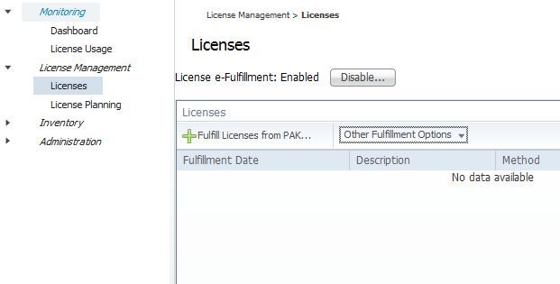
From the licenses screen, select “Other Fulfillment Options,” then “Generate License Request.” The license request window opens.

Copy the text to your clipboard, or download it as a file. Next, we will go to www.cisco.com/go/license, click “Get Demo,” then select “Unified Communications Products,” then “Cisco Unified Communications Demo License Version 9.x.” On the next page, paste in the license request text that was copied from your ELM server, and click “Next.”

On the next page, confirm your email address, registration information, and accept the licensing agreement.

Once you click “Get License,” an email will be sent to you with a zip file attached. Extract the .bin file in the zip file, then go back to the ELM licenses page, and select “Other Fulfillment Options,” then “Fulfill Licenses from File.” Click “Browse,” select the .bin file you downloaded, enter a description if you want, and click “Install.”


Adding a Product Instance to ELM

Now we have the license installed, but the applications are not yet using ELM for licensing. To do this, you add a product instance in ELM. Expand “Inventory,” then click “Product Instances.”

When you click “Add,” The Product Add window opens, allowing you to enter a name, description, IP address or hostname, and authentication information for the product instance you want to add.

The credentials needed are the platform administrator credentials, the ones used for OS Admin, DRS, etc.

When you click OK, ELM will go out to the server you are adding, and update the server to look to ELM for licensing. Once this is done, the page will inform you it is done.

Viewing License Usage in ELM

Once the licenses are synchronized, you can view details of license usage. If licenses at a lower level than those installed are required, the higher level licenses can be borrowed, as seen here. UCM has one user configured, with a single phone, mobility and Presence enabled. This requires an enhanced license, which is “borrowed” from the CUWL Pro licenses that are installed.


Changing the IP address of a server licensed by ELM

One of the benefits of ELM is that you do not need to re-host licenses if you change platform settings, since licensing is no longer tied to a license MAC. However, if you need to change the IP address, you need to follow the proper procedure on ELM. Before you change the IP address, delete the product instance from ELM, follow the proper procedure to update the IP address, and then go through the process to add the product back to ELM. If you do not delete the product instance before updating the IP address, you will get an error adding the instance back into ELM. The fix for this is to run the command “license client reset registration” on the console of the licensed product. Once you run this, the product can be added back into ELM.

Check out the updates for UC 10 Prime License Manager.